
Ultrasound Artifacts: 14 You Will See
Published
Who This Guide Is For
Whether you are a sonography student getting ready for the SPI or a specialty registry, or a practicing sonographer adding a credential, ultrasound artifacts are testable on every ARDMS exam. They also show up every shift in the scan room. This guide walks through the fourteen artifacts you are most likely to see on the boards and at the bedside, with one schematic per artifact, real ultrasound examples from open-access archives, and a consistent breakdown of physics, B-mode appearance, board relevance, and how to recognize or eliminate each one.
A 60-Second Refresher on How a B-Mode Image Is Built
Every artifact below is a violation of one of the four assumptions the B-mode scanner makes when it builds an image: (1) the sound beam travels in a straight line, (2) it travels at exactly 1,540 m/s, (3) the only echoes returning to the probe came from the most recent pulse, and (4) every echo originated from the central axis of the beam. When one of those assumptions breaks, the machine still has to put a dot somewhere on the screen — and an artifact is born. If those four assumptions are unfamiliar, the deeper physics walkthrough at /blog/spi-physics-concepts-ardms-exam and the SPI-specific drill set at /specialty/spi are the right warm-ups before you read this guide.
1. Reverberation Artifact
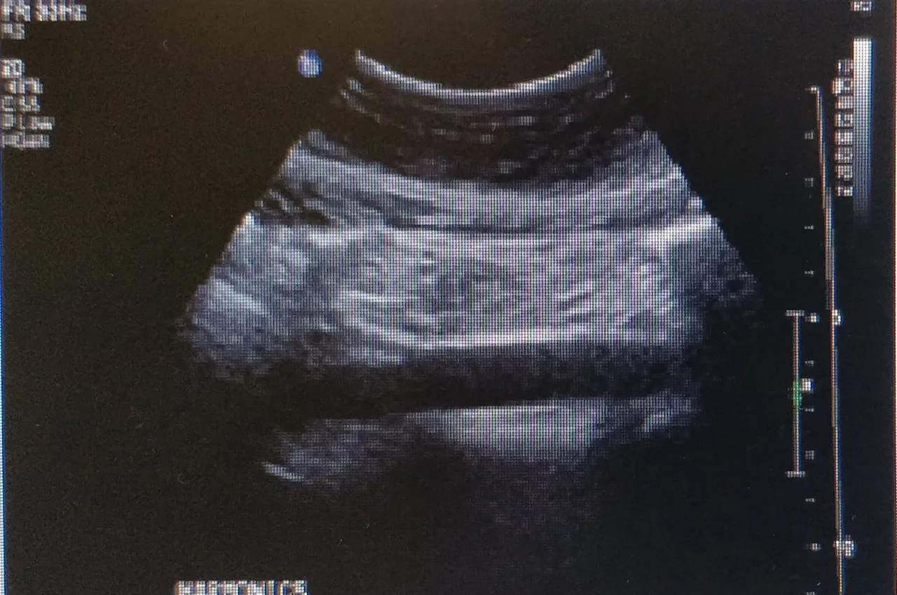
Definition. Equally spaced parallel bright lines deeper than a true strong reflector, caused by sound bouncing repeatedly between two highly reflective surfaces (or between the probe face and a strong reflector).
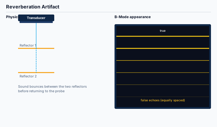
Physics. Each round trip between the two reflectors takes the same amount of time. The machine assumes every returning echo came from a single down-and-back trip and places each successive bounce at the next equally spaced depth.
On the image. A stack of bright parallel lines beneath the true reflector, fading with depth. Classic settings include lung imaging (pleural line and A-lines), needle visualization, bowel gas, and any metal foreign body.
Board relevance. Reverberation is one of the highest-frequency SPI items and shows up across Abdomen, Vascular, and OB stems as either an expected finding (A-lines in normal lung) or a confounder mimicking real anatomy.
Recognize and eliminate. Reduce overall gain, change the angle of insonation, turn on tissue harmonic imaging (which suppresses lower-amplitude bouncing echoes), or reposition so the two reflectors are no longer parallel.
2. Mirror Image Artifact
Definition. A duplicate copy of a real structure displayed deeper than a strong, smooth, curved reflector — most often the diaphragm.
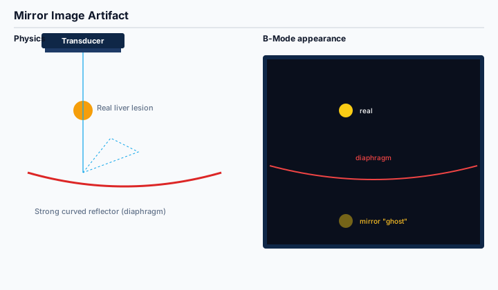
Physics. Sound reflects off the curved reflector, scatters off a real structure on the same side, returns to the reflector, and then back to the probe. The extra round trip is interpreted as additional depth, so the duplicate is mapped on the far side of the mirror.
On the image. An echogenic 'ghost' of the real structure positioned deeper than the strong reflector. The classic setting is liver tissue appearing above the diaphragm, but it is also seen near the bladder wall, pleura, and great vessels.
Board relevance. Tested on Abdomen, OB, and Cardiac items because the duplicate can be mistaken for pleural effusion, pericardial fluid, or a true ectopic mass. Color and spectral Doppler can also produce mirrored Doppler signals.
Recognize and eliminate. Identify the strong curved reflector and look for a structurally identical duplicate just deeper. Decreasing gain, changing the scan plane, and reducing the imaging depth often eliminate the ghost.
3. Comet Tail Artifact
Definition. A short, tapering, bright vertical trail emanating from a small, highly reflective object.
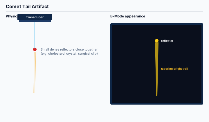
Physics. Two reflective interfaces only a fraction of a wavelength apart trap the sound between them. The closely spaced bounces are misregistered as a continuous, narrowing line of echoes that fades quickly with depth.
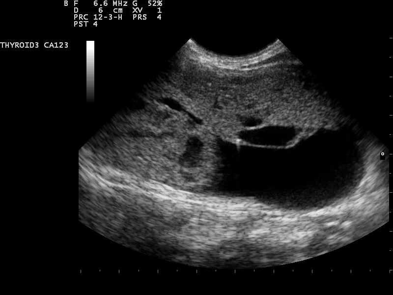
On the image. A bright, short, V-shaped trail. Common sources include cholesterol crystals (adenomyomatosis), surgical clips, IUDs, and biopsy needles.
Board relevance. Comet tail is the cardinal sign for adenomyomatosis on Abdomen items and is a frequent SPI distractor against ring-down. Recognizing the difference is a high-yield discrimination.
Recognize and eliminate. A true comet tail tapers within 1 to 2 cm and is associated with a discrete bright reflector. It is usually preserved (not eliminated) because it is diagnostic.
4. Ring-Down Artifact
Definition. A continuous, solid, bright vertical line beneath a small reflector — most often a tetrahedral cluster of gas bubbles trapping a tiny pocket of fluid that resonates and emits sustained sound back to the probe.
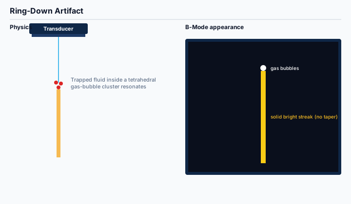
Physics. The trapped fluid is excited by the incoming pulse and then continues to ring at its resonant frequency, sending a sustained signal back to the probe long after the original pulse has passed.
On the image. An unbroken, solid bright line that does not narrow with depth — a key visual difference from comet tail. Most often associated with bowel gas, abscesses, and the lungs in some pathology.
Board relevance. Ring-down vs. comet tail is a classic SPI distinction. The board cue is whether the trail tapers (comet) or stays solid (ring-down).
Recognize and eliminate. Look at the morphology: solid and parallel-walled = ring-down; short and tapering = comet tail. Repositioning the probe rarely eliminates ring-down because the source is intrinsic to the bubble cluster.
5. Side Lobe Artifact
Definition. False echoes placed in the central scan line that actually originated from off-axis reflectors picked up by lower-amplitude side lobes of the beam.
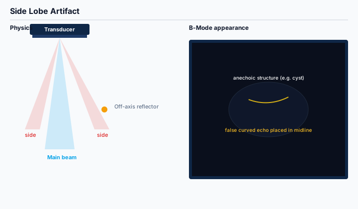
Physics. Real ultrasound beams are not perfect pencils — small amounts of energy radiate off the central axis as side lobes. Strong reflectors lit by a side lobe send echoes back, and the scanner assumes every echo came from the main beam, mapping the off-axis reflector onto the central line.
On the image. Curved or linear low-level echoes inside structures that should be anechoic — a cyst, the gallbladder, or the urinary bladder. The artifact is faint and follows the curvature of the nearby strong reflector.
Board relevance. Side lobe is the classic explanation when an SPI or Abdomen item shows debris inside the gallbladder or bladder that is not real sludge or stone.
Recognize and eliminate. Reduce gain, raise the line density, narrow the sector, change the scan plane, or use harmonic imaging — all suppress side-lobe contributions.
6. Grating Lobe Artifact
Definition. Symmetric off-axis 'ghost' copies of a real reflector caused by the periodic spacing of elements in array transducers.
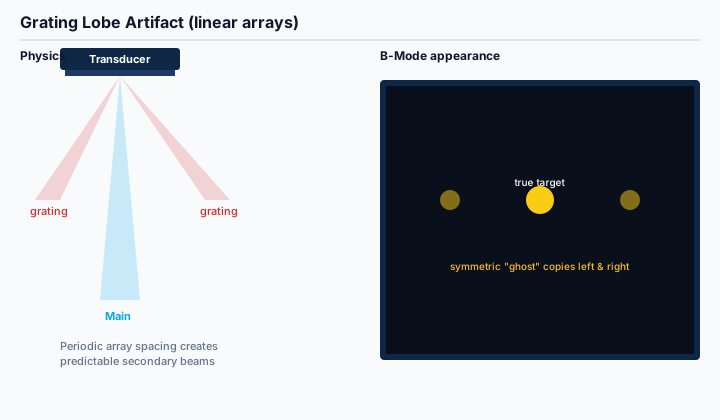
Physics. Equal spacing between transducer elements causes constructive interference at predictable off-axis angles. These secondary 'grating lobes' light up off-axis reflectors that are then misregistered as additional copies of the real target.
On the image. A real bright reflector flanked by symmetric, lower-intensity duplicates at predictable lateral positions. Common in cardiac imaging where strong valve leaflets generate left-and-right ghosts.
Board relevance. Grating lobe is a high-yield SPI item paired with side lobe. The board distinction is array geometry: side lobes occur with any beam, grating lobes only with arrays.
Recognize and eliminate. Modern transducers reduce grating lobes through subdicing and apodization. Practically: reduce gain, change frequency, or use multi-row arrays.
7. Refraction Artifact
Definition. Lateral displacement or duplication of a real structure caused by bending of the sound beam at an interface between tissues with different sound speeds.
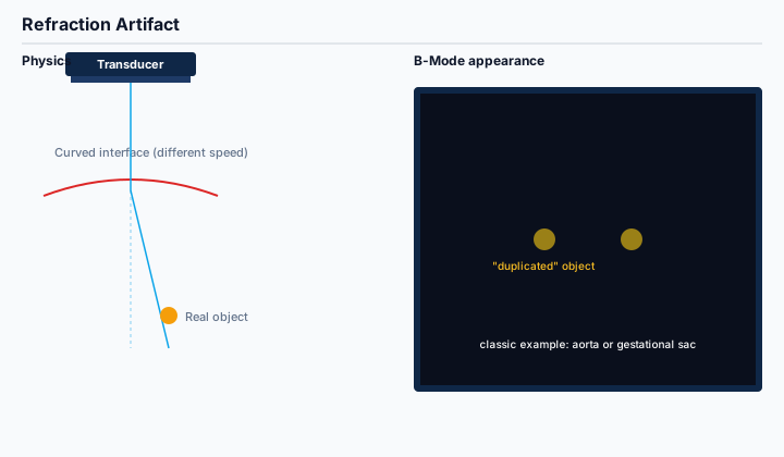
Physics. Snell's law governs bending of the beam at a tissue interface when the angle of incidence is non-perpendicular and the two tissues have different sound speeds. The scanner does not account for this bend and maps the echo on the original straight line.
On the image. A duplicated or laterally shifted structure. Classic settings include the rectus abdominis muscle edges producing a duplicated aorta or gestational sac, and the thyroid producing a 'second' carotid artery.
Board relevance. Refraction is the textbook explanation for the duplicated aorta and the duplicated first-trimester gestational sac on OB items.
Recognize and eliminate. Recognize the symmetric duplication relative to a curved tissue interface. Re-angling the probe so the beam strikes the interface perpendicularly usually resolves the duplication.
8. Acoustic Shadowing
Definition. A dark band beneath a structure that strongly attenuates, reflects, or absorbs the sound beam.
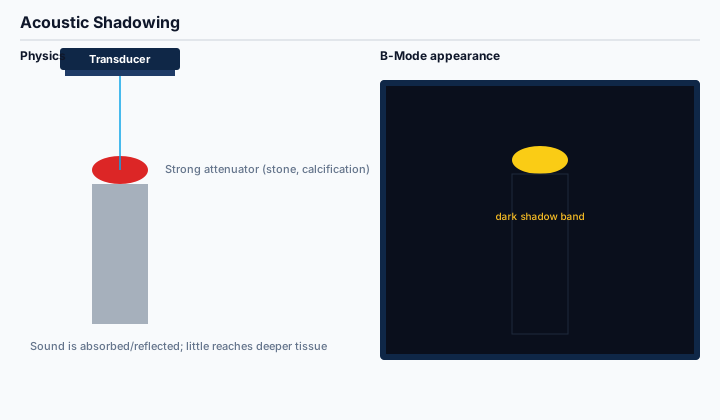
Physics. When a structure absorbs or reflects nearly all of the incident sound, very little energy reaches the deeper tissues. With no returning echoes, the scanner displays a low-amplitude (dark) region.
On the image. A 'clean' anechoic shadow beneath stones, calcifications, and the cortex of bone, and a 'dirty' shadow beneath gas (because gas reflects with reverberation rather than absorbing cleanly).
Board relevance. Shadowing is the diagnostic finding for cholelithiasis, renal calculi, and bone, and it is the pathognomonic visual on Abdomen, Pediatric, and MSK items.
Recognize and eliminate. Shadowing is usually preserved as a diagnostic feature, but spatial compounding and harmonic imaging can soften it. Edge-shadowing from the curved walls of round structures (gallbladder neck, simple cyst) is a separate refractive variant.
9. Posterior Acoustic Enhancement
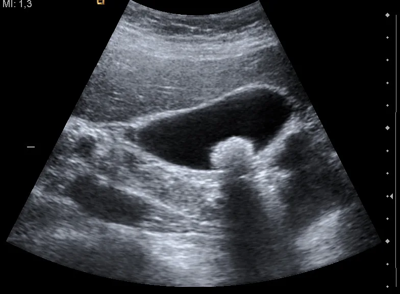
Definition. A bright band of tissue immediately deeper than a fluid-filled structure that attenuates very little sound.
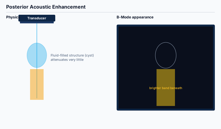
Physics. Time-gain compensation assumes a uniform tissue attenuation rate. Fluid attenuates less than soft tissue, so signals from beneath the cyst are over-amplified by TGC and displayed as a brighter region.
On the image. A wedge or column of brighter tissue directly beneath simple cysts, the gallbladder, the urinary bladder, and abscesses with mostly fluid content.
Board relevance. Enhancement is the textbook secondary feature confirming a structure is fluid-filled rather than solid. Frequently paired with shadowing on Abdomen, Breast, and OB items.
Recognize and eliminate. Usually preserved as a diagnostic feature. Manual TGC adjustment and uniform gain settings reduce its prominence when needed.
10. Anisotropy
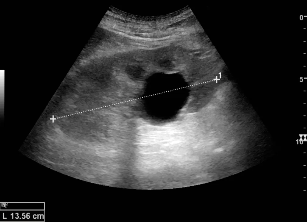
Definition. Apparent change in echogenicity of fibrillar structures (tendons, muscles, nerves) based purely on the angle between the beam and the fibers.
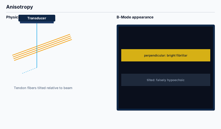
Physics. The fibrillar microstructure of tendons, muscles, and nerves reflects sound most strongly when the beam strikes it perpendicularly. Even a few degrees of tilt scatters the returning echoes away from the probe and drops the apparent echogenicity.
On the image. A tendon that is bright and striated in one image becomes dark in the next without any pathology change. The classic mistake is calling normal tilted tendon a 'tendon tear'.
Board relevance. Anisotropy is central to MSK imaging and can appear as a confounder on Vascular and OB items as well.
Recognize and eliminate. Heel-toe rocking the probe to keep the beam perpendicular to the fibers, beam steering on linear arrays, and spatial compounding all reduce anisotropy. The /blog/msk-ultrasound-credential-right-for-you primer is a good companion read for MSK candidates.
11. Slice-Thickness (Partial Volume) Artifact
Definition. False low-level echoes appearing inside the edge of an anechoic structure because the elevational slice of the beam includes adjacent solid tissue.
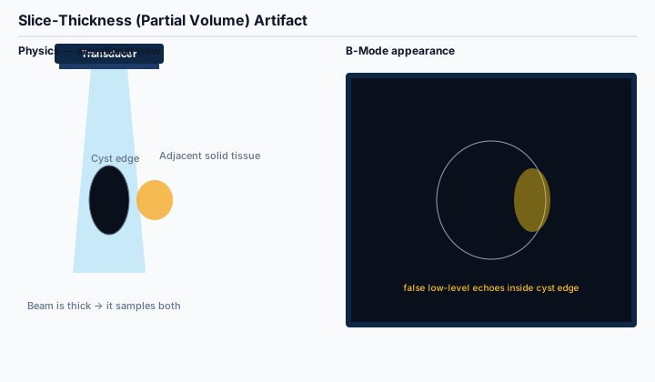
Physics. The ultrasound beam has a measurable thickness in the elevational plane (perpendicular to the imaging plane). At the edge of a cyst, the beam straddles both the fluid and adjacent solid tissue, and the average appears as low-level echoes inside the cyst.
On the image. A cyst that should be completely anechoic shows low-level echoes near its margin — easily mistaken for sludge or hemorrhage.
Board relevance. Slice-thickness is the textbook explanation for 'pseudo-sludge' inside the gallbladder or urinary bladder and shows up on SPI and Abdomen items.
Recognize and eliminate. Re-center the cyst in the field of view, adjust the elevational focus, switch to a higher-frequency probe with a thinner slice, or scan the cyst from a different plane.
12. Range Ambiguity
Definition. A deep echo from a previous pulse that is misregistered shallow on the next image when the pulse repetition frequency is too high for the imaging depth.
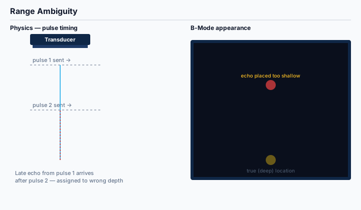
Physics. The scanner assumes every returning echo came from the most recent pulse. If a deep echo from a previous pulse arrives after the next pulse has been transmitted, the scanner assigns it to the new pulse and places it at a shallower depth than it actually came from.
On the image. A deep structure appearing as a faint duplicate higher in the frame, often without clear anatomical correlation.
Board relevance. Range ambiguity is the standard SPI explanation for the trade-off between PRF, frame rate, and maximum imaging depth — heavily tested on physics items.
Recognize and eliminate. Decrease PRF (or increase imaging depth, which automatically lowers PRF), or accept a lower frame rate. Most modern scanners limit PRF based on selected depth to prevent this.
13. Speed-of-Sound (Range) Error
Definition. Misregistration of structure depth caused by tissue with a sound speed that differs from the assumed 1,540 m/s.
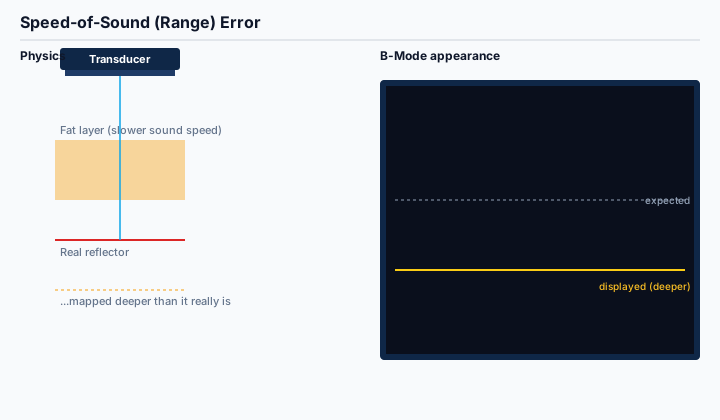
Physics. The scanner converts round-trip time to depth using a fixed assumption of 1,540 m/s. If the beam crosses tissue with a different speed (fat is ~1,450 m/s, bone is ~4,080 m/s), the calculated depth is wrong.
On the image. Boundaries appear stepped or displaced where they should be smooth — most visible in obese patients (fat-induced delay) and where bone underlies soft tissue.
Board relevance. A core SPI physics item: candidates must know the assumed propagation speed and which tissues violate it.
Recognize and eliminate. Recognize the displacement at fat–muscle or fat–solid-organ interfaces. Some advanced systems support sound-speed correction; otherwise the artifact is intrinsic.
14. Twinkling Artifact
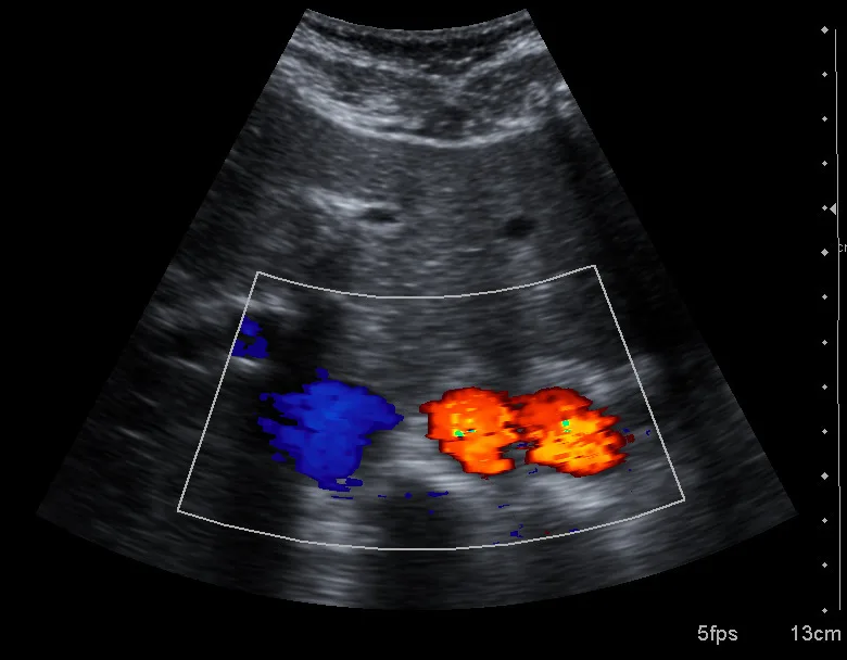
Definition. A rapid mosaic of color Doppler signal posterior to a rough or granular reflector — most famously a kidney stone.
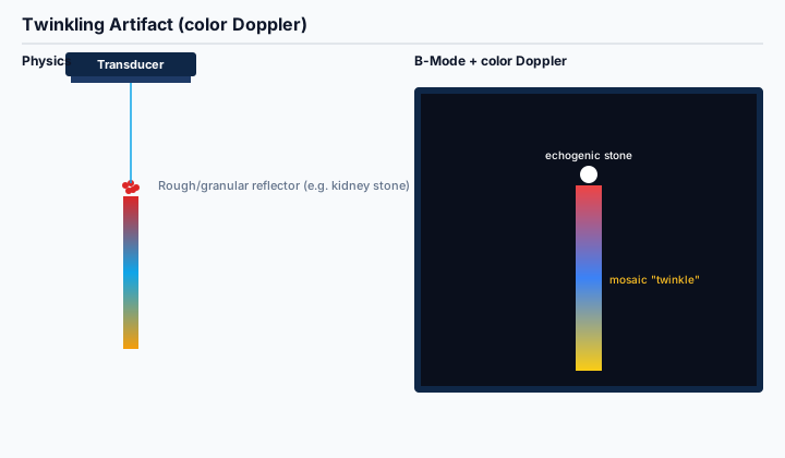
Physics. The granular surface of a stone produces complex, time-varying echoes that the color Doppler algorithm cannot phase-resolve. The processor labels these as motion and assigns a rapidly changing mosaic of colors.
On the image. A flickering red-blue-yellow trail directly posterior to an echogenic focus with or without acoustic shadowing — highly specific for stone disease in the kidney, ureter, gallbladder, or biliary tree.
Board relevance. Twinkling is increasingly tested on Abdomen and Vascular items as a way to confirm small stones that do not yet shadow.
Recognize and eliminate. Twinkling is a feature, not a bug — it is preserved diagnostically. Adjusting color gain, write priority, and PRF can enhance or reduce its prominence.
How Artifacts Show Up on the Boards
ARDMS specialty exams and the SPI test ultrasound artifacts in three common ways. First, image-based items show a B-mode (occasionally color Doppler) appearance and ask which artifact is responsible — recognition is the entire skill. Second, physics items present a scenario (pulse repetition frequency, beam geometry, tissue interface) and ask what artifact would result, which means you need to reason from cause to appearance. Third, clinical items embed an artifact inside a vignette and ask whether the finding is real (e.g., 'is there sludge in the gallbladder?'); the right answer often hinges on naming the artifact rather than the pathology.
Exam Tip: When a board image looks like an artifact, work the cause-and-effect chain in both directions. From the image, ask 'what physics assumption was violated to produce this appearance?' From the stem, ask 'what would the screen actually show if that assumption broke?' Moving fluently in both directions is what gets artifact items right under time pressure on test day.
The full set of artifacts is split across all seven specialty content outlines but is most heavily weighted on the SPI exam. The /specialty/spi bank lets you drill artifact recognition under timed conditions, and the specialty banks at /specialties cover the clinical side.
Frequently Asked Questions
Q: Are artifacts always bad?
No. Several artifacts are diagnostic features rather than imaging errors. Acoustic shadowing confirms a stone. Posterior enhancement confirms a fluid-filled structure. Comet tail confirms cholesterol crystals in adenomyomatosis. Twinkling confirms a small stone before it shadows. The skill is recognizing which artifacts to preserve and which to eliminate.
Q: What is the single fastest way to suppress most reverberation, side lobe, and slice-thickness artifacts at once?
Tissue harmonic imaging. Harmonic imaging suppresses lower-amplitude off-axis and reverberating signals more aggressively than the fundamental, which cleans up reverberation, side lobes, and edge slice-thickness echoes in a single setting change. It is the highest-yield 'one knob' answer on board items that ask for a single corrective action.
Q: How do I tell comet tail from ring-down on a board image?
Look at the trail. Comet tail tapers and fades within 1 to 2 cm of the source. Ring-down stays solid and parallel-walled and extends much further into the image. Comet tail is associated with focal cholesterol crystals or surgical clips; ring-down is associated with bowel gas and resonant fluid pockets.
Q: Which artifacts are most heavily tested on the SPI exam specifically?
Reverberation, side lobe, grating lobe, range ambiguity, slice thickness, and speed-of-sound error are core SPI physics items because they map directly to the four imaging assumptions covered in the SPI content outline. The complete walkthrough at /blog/ardms-spi-exam-complete-guide and /blog/spi-physics-concepts-ardms-exam covers the supporting physics in detail.
Q: I am a working sonographer adding a credential. Do I need to re-learn artifacts from scratch?
Usually not. Working sonographers recognize artifacts visually every day. The board exam asks you to name them and explain the underlying physics, which is the part that often atrophies. Re-reading this guide and drilling 30 to 50 artifact items on /specialty/spi in the two weeks before your exam is typically enough to refresh the formal vocabulary.
Q: Can AI scanners eventually eliminate artifacts entirely?
Most artifacts are intrinsic to how sound interacts with tissue, not to the scanner software, so they cannot be eliminated entirely. Modern systems do reduce many of them — multi-frequency probes, harmonic imaging, spatial compounding, and AI-assisted noise reduction all help — but candidates and clinicians will still need to recognize artifacts for the foreseeable future. Our broader take on AI in sonography lives at /blog/future-of-ultrasound-in-ai-age.
Conclusion: Artifacts Are a Vocabulary, Not a Mystery
Every ultrasound artifact in this guide is the predictable consequence of a specific physics assumption breaking. Once you can name the assumption, the appearance, and the corrective maneuver for each of the fourteen artifacts above, the artifact items on the SPI and on every specialty exam become a reliable source of points rather than a source of anxiety. Pair this guide with the SPI study walkthrough at /blog/ardms-spi-exam-complete-guide and the 90-day study framework at /blog/90-day-ardms-study-plan, then drill image-based artifact items on /specialty/spi until recognition is automatic.
All real ultrasound images in this guide are sourced from Wikimedia Commons and are reproduced under their respective Creative Commons licenses; full attribution appears in each caption and in the Sources list below.
Sources
- Reverberation artefact (CC BY-SA 4.0) — Wikimedia Commons / User:Dv3163
- Comet tail artifacts from thyroid colloid (CC BY-SA 3.0) — Wikimedia Commons / Nevit Dilmen
- Ultrasound image of impacted gallstone with shadowing (CC BY-SA 3.0) — Wikimedia Commons / Nevit Dilmen
- Aorta duplication (refraction) artifact (CC BY-SA 3.0) — Wikimedia Commons / Nevit Dilmen
- Simple renal cyst with posterior enhancement (CC BY 4.0) — Hansen, Nielsen, Ewertsen — Diagnostics 2015
- ARDMS SPI Examination Content Outline — ARDMS
- Ultrasound Artifacts — RadiologyKey overview — RadiologyKey
If you find this article helpful and want to put the strategies into practice, sign up for an Ultrasound Analytics account to access the full ARDMS-aligned question bank, AI tutoring on every missed answer, full-length timed exams, and the analytics dashboard that translates your performance into a Readiness Score for each specialty registration.